Project introduction
The following tutorial shows you how to use the STONE STVC050WT-01 touch display module to make a simple home appliance control system.
STONE STVC050WT - 01 the support touch display module is 5 inches, 480 * 272 resolution on the module has been integrated display and touch screen driver needed chips, developers need only on the STONE, the official VGUS design software related UI interface design and generate a programming file downloaded to the STONE display module, and then through a serial port (RS232 / RS485 / TTL) correspond with it, you can perform complex UI design aspects.
The process is as follows:
The following image shows some parameters of the STONE STVC050WT-01 display module:
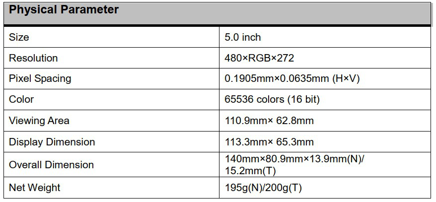
This display module is just one of many in this line of products. There are many other display modules available in different configurations. www.stoneitech.com
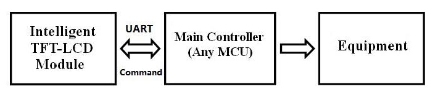
STONE display module development three steps:
- Designed the UI with STONE TOOL softwareand downloaded the design file to the display module.
- MCU communicates with STONE display module through serial port.
- The MCU performs other actions based on the data obtained in step
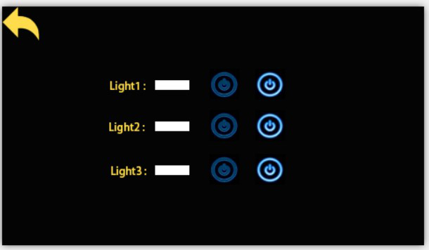
Today we made a simple home appliance control. Through Photoshop, I designed the following simple interface:
Function:
when the light button is pressed, the page jumps to 2, showing the switch state of three lights.When the on/off light button is pressed, the serial port of the screen module issues the switch signal protocol.The external MCU can send data directly to the screen module through a serial port. Let the screen display the light switch state directly.
New project with STONE Display
On STONE's website, we can download the latest version of TOOLS 2019 software, through which we can design the UI:
STONE TOOL is a GUI design software that requires no installation. After downloading, it can be directly opened and run by decompression. It should be noted that this software needs to be run in a compatible way on Windows8 and Windows10 systems
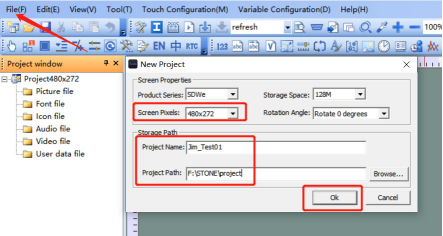
Since I'm using STVC050WT-01 with a resolution of 480*272 and the default Flash space size of 128Mbyte (expandable to 1024MByte), I've chosen 128Mbyte.
Set the project name and storage path, and click "OK" to complete.
Right-click the "Picture" directory and delete 0.jpg:
Add UI image in the STONE TOOLS:
Right-click the "picture" directory and add the two UI ICONS we have prepared to the project:
Add the word stock in STONE TOOLS
Right mouse click "Font file", select the appropriate Font to add to the project. Here I chose ASCII 24 by 48.
Add a button:
We need to set a function on the "Light" button in the first UI on the STONE TOOL software:
when we click the "Light" button, we will jump to the second page. How to do it?
Click the "Button" icon to draw the area of the Button:
The yellow area represents the button area that the user has drawn. Button properties are listed in the properties bar on the right of STONE TOOL software:
Just set the "pageswitch" option to 1 to switch to the second page when the button is pressed.
"Generating configuration file" in "Tool" and then "Virtual serial port screen".
Then we go ahead and change the arrow in the top left corner of page 2 to a button:
When the user presses this button, it returns to the first page.
Add text display:
Using the Text variable control, circle the white space after "light1" :
Then click the Text Variable just added, and the property interface will appear on the right of STONE TOOL software, mainly changing the following parameters:
Among them, "Variable memory addree" refers to the memory address where the displayed content is stored. One address can store two bytes. Our default display content is "OFF", which requires three bytes of memory space. This means that we store "OFF" in address 0020 and 0021.
A button with a return value:
The control we used above is "Button". This "Button" control does not return a value, which means that when the user presses the Button, the serial port of the display module does not send data to the MCU.
If the user pressed the button and wants the screen module to return data to the MCU, we can use the "return pressed key-value" control:
The property bar is set as follows:
Download the UI design file to the display module:
- Plug the USB flash drive into the computer
- Click the Download to u-disk button on the STONE TOOl
- Pull out the USB flash disk
- Insert the USB disk into the USB interface of the display module and wait for the completion of the upgrade. When the upgrade is completed, there will be a prompt sound
- tes
A serial port communication
Key-value return
After downloading the program to the display module, turn it on, connect the computer through the serial port via USB-TTL, press the light button of Light1, and return the serial port data: a55a 06 83 00 26 01 00 A8

Press the button to turn off the light
Serial data return: A5 5A 06 83 00 26 01 00 A9

A5 5A: frame header
06: instruction byte length, 83 00 26 01 00 A9 total 6 bytes (excluding data frame header)
83: read variable memory instruction
00 26: variable storage address
01: data word length, 00 A9, 1-word length (2 Byte)
00 A9: user data content, depending on the keys set.
Write register data
This instruction writes 55 aa to address 0x0020 in the data storage area:
0xA5 0x5A 0x05 0x82 0x00 0x20 0x55 0xaa
Since we've set Light1's text display storage address to 0x0020, writing data to this address using a serial port is equivalent to changing the content of Light1's text display box.
Read register data
The serial port sends the following command to the display module:
0xA5 0x5A 0x03 0x83 0x00 0x20
Represents the value of reading 0x0020, and in the change project, represents t he switch state of the read-lamp.
Comments
Post a Comment