Introduction to display screen
This document will teach you how to use a STM32 MCU +MPU6050 accelerometer gyroscope sensor +STONE STVC070WT serial port display for a DEMO.
STVC070WT is the serial display of our company, its development is simple, easy to use, you can go to the website of our company for all display difference: https://www.stoneitech.com/
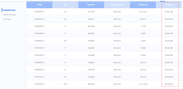
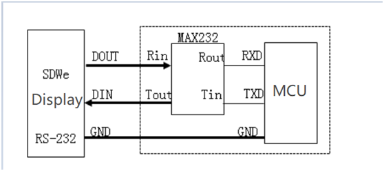
It is worth noting that our screen supports serial port communication. Some models support TTL/RS232/RS485, but some only support RS232. If your MCU's serial port is TTL logic level, you need to add an MAX3232 for level conversion.If you want to know which screen supports TTL and which supports both TTL and RS232, you can check it out on our website:
https://www.stoneitech.com/product/industrial-type
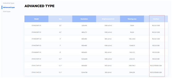
https://www.stoneitech.com/product/advanced-type
https://www.stoneitech.com/product/civil-type
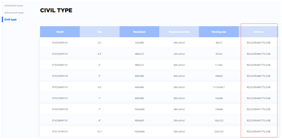
We can see that "industrial type" and "advanced type" screens generally only support RS232 or RS485, and only "civilian type" screens can support TTL/RS232/RS485.
If you choose the "advanced type" or "industrial type", but your SCM only supports TTL, then you need to do the following conversion:
Other relevant information can be viewed or downloaded on the official website:
https://www.stoneitech.com/support/download
Three steps of STONE display screen development:
l Design the display logic and button logic with STONE TOOL software, and download the design file to the display module.
l The MCU communicates with the STONE display module through a serial port.
l With the data obtained in step 2, the MCU does other actions.
Project introduction
What I'm going to show you today is a Demo of gravity, gyroscope, euler Angle,
Functions are as follows:
l Three text boxes display acceleration values
l Three text boxes display gyroscope values
l Three text boxes display euler Angle values
l A text box displays the current refresh time
l Two buttons adjust the refresh time
First, we need to use Photoshop to design two UI interfaces, and the design results are as follows:
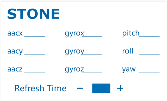

The first image is the main screen image, and the second image is the button effect.
Then we open "TOOL2019" and design the effects in the TOOL:
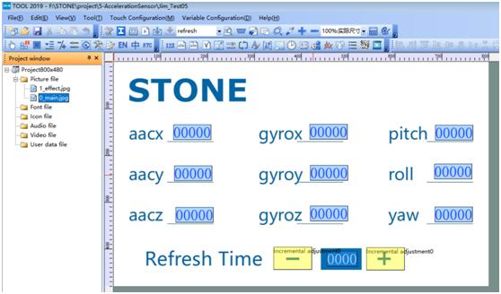
Two main components are used:
Numerical display unit
Incremental button
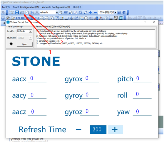
After the design, the simulation operation effect can be seen in the simulation interface:
MPU-6050

The mpu-6050 is the world's first integrated 6-axis motion processing chip. Compared with the multi-component solution, it eliminates the problem of the difference between the combined gyroscope and the accelerator time axis and reduces a lot of packaging space.When connected to the three-axis magnetometer timing, the mpu-6050 provides a complete 9-axis motion fusion output to the I2C or SPI ports (SPI is only available on the mpu-6000).
Sensing range
The angular velocity sensing range of mpu-6050 is ±250, ±500, ±1000 and ±2000°/ SEC (DPS), which can accurately track fast and slow actions. Moreover, users can program and control the detection range of accelerators to be ±2g, ±4g±8g and ±16g.Product data can be transmitted via IIC up to 400kHz or SPI up to 20MHz (SPI is only available on mpu-6000).Mpu-6050 can work under different voltages, the voltage supply of VDD is 2.5v ±5%, 3.0v ±5% or 3.3v ±5%, and the power supply of logic interface VDDIO is 1.8v ±5% (VDD only is used for MPU6000).The mpu-6050's packaging size of 4x4x0.9mm(QFN) is revolutionary in the industry.Other features include built-in temperature sensors and oscillators that vary only ±1% in the operating environment.
Application
Mobile sensing games, augmented reality, EIS: Electronic Image Stabilization (OIS: Optical Image Stabilization) user interface of pedestrian navigator with "zero touch" gesture.
Smart phone, tablet device, handheld game product, game console, 3D remote control, portable navigation device, uav, balance car.
Characteristics
Digital output of 6 - or 9-axis rotation matrix, quaternion, Euler Angle forma fusion calculus data.3-axis angular velocity sensor (gyroscope) with 131 LSBs/°/ SEC sensitivity and full grid sensing range of ±250, ±500, ±1000 and ±2000°/ SEC.It can be controlled by program, and the program control range is ±2g, ±4g, ±8g and ±16g.Remove the sensitivity between the accelerator and the gyroscope axis and reduce the influence of the Settings and sensor drift.The DMP (Digital Motion Processing) engine reduces the load of complex fusion algorithms, sensor synchronization, postural sensing, etc.The motion processing database supports the operating time deviation and magnetic sensor correction algorithms built in Android, Linux and Windows.Temperature sensor with digital output and digital input Sync pin support video electronic shadow phase stabilization technology and GPS programmable control interrupt support gesture recognition, shake, zoom in and out of the picture, rolling, rapid descent interrupt, high-g interrupt, zero motion sensing, touch sensing, shake sensing.The supply voltage of VDD is 2.5v ±5%, 3.0v ±5% and 3.3v ±5%.The operating current of VDDIO is 1.8v ± 5% : 5mA;Standby current of gyroscope: 5uA;Accelerator operating current: 350uA, accelerator power-saving mode current: 20uA@10Hz I2C in fast mode up to 400kHz, or SPI serial host interface up to 20MHz built in frequency generator at full temperature range only ±1% frequency variation.The minimum and thinnest packaging (4x4x0.9mm QFN) tailored for portable products has been tested to meet RoHS and environmental standards.
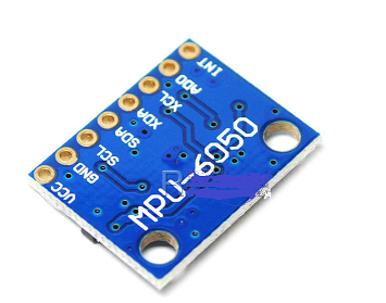
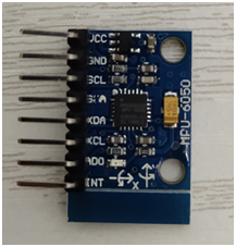
About the pin
SCL and SDA connect to the IIC interface of MCU, through which MCU controls MPU6050.
There is also an IIC interface, AXCL and XDA, which can be used to connect external slave devices, such as magnetic sensors, to form a nine-axis sensor.VLOGIC is the voltage of IO port, and the lowest pin can reach 1.8v. Generally, we can directly use VDD.AD0 is the address control pin from the IIC interface (connected to MCU), which controls the lowest order of the IIC address.If GND is connected, then the IIC address of MPU6050 is 0X68 and 0X69 if VDD is connected. Note: the address here does not contain the lowest order of data transfer (the lowest order is used for reading and writing).
Below is the mpu-6050 module I used:
STM32 microcontroller
STM32F103RCT6 MCU has powerful functions. Here are the basic parameters of the MCU:
l Series: STM32F10X
l Kernel: ARM - COTEX32
l Speed: 72 MHZ
l Communication interface: CAN, I2C, IrDA, LIN, SPI, UART/USART, USB
l Peripheral equipment: DMA, motor control PWM, PDR, POR, PVD, PWM, temperature sensor, WDT
l Program storage capacity: 256KB
l Program memory type: FLASH
l RAM capacity: 48K
l Voltage - power supply (Vcc/Vdd) : 2 V ~ 3.6 V
l Oscillator: internal
l Operating temperature: -40°C ~ 85°C
l Package/housing: 64-lqfp
In this project, I will use UART, GPIO, Watch Dog and Timer of STM32F103RCT6.
The following is the code development record for the project.
STM32 USES Keil MDK software development, about which you must be familiar, so I will not introduce the installation method of this software.
STM32 can be simulated online through j-link or st-link and other simulation tools. The following picture is the STM32 development board I used:
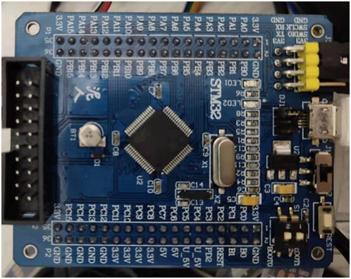
Add serial driver
STM32F103RCT6 has several serial ports. In this project, I used the serial port channel PA9/PA10, and the serial port baud rate was set at 115200.
The associated serial port initialization code can be seen below:
u16 USART_RX_STA=0;
void uart_init(u32 bound){
//GPIO
GPIO_InitTypeDef GPIO_InitStructure;
USART_InitTypeDef USART_InitStructure;
NVIC_InitTypeDef NVIC_InitStructure;
RCC_APB2PeriphClockCmd(RCC_APB2Periph_USART1|RCC_APB2Periph_GPIOA, ENABLE); //ʹÄÜUSART1£¬GPIOAʱÖÓ
//USART1_TX GPIOA.9
GPIO_InitStructure.GPIO_Pin = GPIO_Pin_9; //PA.9
GPIO_InitStructure.GPIO_Speed = GPIO_Speed_50MHz;
GPIO_InitStructure.GPIO_Mode = GPIO_Mode_AF_PP;
GPIO_Init(GPIOA, &GPIO_InitStructure);//INIT GPIOA.9
//USART1_RX GPIOA.10 INIT
GPIO_InitStructure.GPIO_Pin = GPIO_Pin_10;//PA10
GPIO_InitStructure.GPIO_Mode = GPIO_Mode_IN_FLOATING;//FLOTING
GPIO_Init(GPIOA, &GPIO_InitStructure);//INIT GPIOA.10
//Usart1 NVIC
NVIC_InitStructure.NVIC_IRQChannel = USART1_IRQn;
NVIC_InitStructure.NVIC_IRQChannelPreemptionPriority=3 ;
NVIC_InitStructure.NVIC_IRQChannelSubPriority = 3;
NVIC_InitStructure.NVIC_IRQChannelCmd = ENABLE;
NVIC_Init(&NVIC_InitStructure);
//USART
USART_InitStructure.USART_BaudRate = bound;
USART_InitStructure.USART_WordLength = USART_WordLength_8b;
USART_InitStructure.USART_StopBits = USART_StopBits_1;
USART_InitStructure.USART_Parity = USART_Parity_No;
USART_InitStructure.USART_HardwareFlowControl = USART_HardwareFlowControl_None;
USART_InitStructure.USART_Mode = USART_Mode_Rx | USART_Mode_Tx;
USART_Init(USART1, &USART_InitStructure);
USART_ITConfig(USART1, USART_IT_RXNE, ENABLE);
USART_Cmd(USART1, ENABLE);
}
u8 USART_RX_END=0;
void USART1_IRQHandler(void) //Uart1 handler
{
u8 Res;
if(USART_GetITStatus(USART1, USART_IT_RXNE) != RESET)
{
if(USART_RX_END==0)
{
Res =USART_ReceiveData(USART1);
USART_RX_BUF[USART_RX_STA]=Res ;
USART_RX_STA++;
if(USART_RX_STA>8)
{
USART_RX_END=1;
}
}
}
}
Watch Dog
To prevent the system from crashing while the program was running, I added the watchdog.In fact, all projects that use the MCU generally use a watchdog.
STM32 has two built-in watchdogs, providing greater security, time accuracy and flexibility.Two watchdog devices (independent watchdog and window watchdog) can be used to detect and resolve faults caused by software errors.When the counter reaches a given timeout value, an interrupt (window watchdog only) or system reset is triggered.
l Independent watchdog (IWDG)
Driven by a dedicated low speed clock (LSI), it works even if the master clock fails.
It is suitable for use in situations where the watchdog is required to work completely independently outside the main program and requires low time accuracy.
l Window watchdog (WWDG)
Clock driver obtained from APB1 clock frequency division.Detect abnormal application operations through a configurable time window.Suitable for programs that require watchdogs to function in precise timing Windows.
Because of this DEMO program, I will not add the watchdog function.
MPU-6050Driver
This code USES IIC communication mode to read the data of MPU6050, and IIC communication USES software simulation IIC. There are many related codes, so I won't paste them here.
The following code is the driver for MPU6050:
#include "mpu6050.h"
#include "sys.h"
#include "delay.h"
#include "usart.h"
u8 MPU_Init(void)
{
u8 res;
GPIO_InitTypeDef GPIO_InitStructure;
RCC_APB2PeriphClockCmd(RCC_APB2Periph_AFIO,ENABLE);
RCC_APB2PeriphClockCmd(RCC_APB2Periph_GPIOA,ENABLE);
GPIO_InitStructure.GPIO_Pin = GPIO_Pin_15;
GPIO_InitStructure.GPIO_Mode = GPIO_Mode_Out_PP;
GPIO_InitStructure.GPIO_Speed = GPIO_Speed_50MHz;
GPIO_Init(GPIOA, &GPIO_InitStructure);
GPIO_PinRemapConfig(GPIO_Remap_SWJ_JTAGDisable,ENABLE);
MPU_AD0_CTRL=0;
MPU_IIC_Init();
MPU_Write_Byte(MPU_PWR_MGMT1_REG,0X80);
delay_ms(100);
MPU_Write_Byte(MPU_PWR_MGMT1_REG,0X00);
MPU_Set_Gyro_Fsr(3);
MPU_Set_Accel_Fsr(0);
MPU_Set_Rate(50);
MPU_Write_Byte(MPU_INT_EN_REG,0X00);
MPU_Write_Byte(MPU_USER_CTRL_REG,0X00);
MPU_Write_Byte(MPU_FIFO_EN_REG,0X00);
MPU_Write_Byte(MPU_INTBP_CFG_REG,0X80);
res=MPU_Read_Byte(MPU_DEVICE_ID_REG);
if(res==MPU_ADDR)
{
MPU_Write_Byte(MPU_PWR_MGMT1_REG,0X01);
MPU_Write_Byte(MPU_PWR_MGMT2_REG,0X00);
MPU_Set_Rate(50);
}else return 1;
return 0;
}
u8 MPU_Set_Gyro_Fsr(u8 fsr)
{
return MPU_Write_Byte(MPU_GYRO_CFG_REG,fsr<<3);
}
u8 MPU_Set_Accel_Fsr(u8 fsr)
{
return MPU_Write_Byte(MPU_ACCEL_CFG_REG,fsr<<3);
}
u8 MPU_Set_LPF(u16 lpf)
{
u8 data=0;
if(lpf>=188)data=1;
else if(lpf>=98)data=2;
else if(lpf>=42)data=3;
else if(lpf>=20)data=4;
else if(lpf>=10)data=5;
else data=6;
return MPU_Write_Byte(MPU_CFG_REG,data);
}
u8 MPU_Set_Rate(u16 rate)
{
u8 data;
if(rate>1000)rate=1000;
if(rate<4)rate=4;
data=1000/rate-1;
data=MPU_Write_Byte(MPU_SAMPLE_RATE_REG,data);
return MPU_Set_LPF(rate/2);
}
short MPU_Get_Temperature(void)
{
u8 buf[2];
short raw;
float temp;
MPU_Read_Len(MPU_ADDR,MPU_TEMP_OUTH_REG,2,buf);
raw=((u16)buf[0]<<8)|buf[1];
temp=36.53+((double)raw)/340;
return temp*100;;
}
u8 MPU_Get_Gyroscope(short *gx,short *gy,short *gz)
{
u8 buf[6],res;
res=MPU_Read_Len(MPU_ADDR,MPU_GYRO_XOUTH_REG,6,buf);
if(res==0)
{
*gx=((u16)buf[0]<<8)|buf[1];
*gy=((u16)buf[2]<<8)|buf[3];
*gz=((u16)buf[4]<<8)|buf[5];
}
return res;;
}
u8 MPU_Get_Accelerometer(short *ax,short *ay,short *az)
{
u8 buf[6],res;
res=MPU_Read_Len(MPU_ADDR,MPU_ACCEL_XOUTH_REG,6,buf);
if(res==0)
{
*ax=((u16)buf[0]<<8)|buf[1];
*ay=((u16)buf[2]<<8)|buf[3];
*az=((u16)buf[4]<<8)|buf[5];
}
return res;;
}
u8 MPU_Write_Len(u8 addr,u8 reg,u8 len,u8 *buf)
{
u8 i;
MPU_IIC_Start();
MPU_IIC_Send_Byte((addr<<1)|0);
if(MPU_IIC_Wait_Ack())
{
MPU_IIC_Stop();
return 1;
}
MPU_IIC_Send_Byte(reg);
MPU_IIC_Wait_Ack();
for(i=0;i<len;i++)
{
MPU_IIC_Send_Byte(buf[i]);
if(MPU_IIC_Wait_Ack())
{
MPU_IIC_Stop();
return 1;
}
}
MPU_IIC_Stop();
return 0;
}
u8 MPU_Read_Len(u8 addr,u8 reg,u8 len,u8 *buf)
{
MPU_IIC_Start();
MPU_IIC_Send_Byte((addr<<1)|0);
if(MPU_IIC_Wait_Ack())
{
MPU_IIC_Stop();
return 1;
}
MPU_IIC_Send_Byte(reg);
MPU_IIC_Wait_Ack();
MPU_IIC_Start();
MPU_IIC_Send_Byte((addr<<1)|1);
MPU_IIC_Wait_Ack();
while(len)
{
if(len==1)*buf=MPU_IIC_Read_Byte(0);
else *buf=MPU_IIC_Read_Byte(1);
len--;
buf++;
}
MPU_IIC_Stop();
return 0;
}
u8 MPU_Write_Byte(u8 reg,u8 data)
{
MPU_IIC_Start();
MPU_IIC_Send_Byte((MPU_ADDR<<1)|0);
if(MPU_IIC_Wait_Ack())
{
MPU_IIC_Stop();
return 1;
}
MPU_IIC_Send_Byte(reg);
MPU_IIC_Wait_Ack();
MPU_IIC_Send_Byte(data);
if(MPU_IIC_Wait_Ack())
{
MPU_IIC_Stop();
return 1;
}
MPU_IIC_Stop();
return 0;
}
u8 MPU_Read_Byte(u8 reg)
{
u8 res;
MPU_IIC_Start();
MPU_IIC_Send_Byte((MPU_ADDR<<1)|0);
MPU_IIC_Wait_Ack();
MPU_IIC_Send_Byte(reg);
MPU_IIC_Wait_Ack();
MPU_IIC_Start();
MPU_IIC_Send_Byte((MPU_ADDR<<1)|1);
MPU_IIC_Wait_Ack();
res=MPU_IIC_Read_Byte(0);
MPU_IIC_Stop();
return res;
}
Main Function
The full code content of the main.c file is as follows:
#include "led.h"
#include "delay.h"
#include "key.h"
#include "sys.h"
#include "lcd.h"
#include "usart.h"
#include "mpu6050.h"
#include "usmart.h"
#include "inv_mpu.h"
#include "inv_mpu_dmp_motion_driver.h"
extern u8 USART_RX_END;
#define aacx_h 0x00
#define aacx_l 0x01
#define aacy_h 0x00
#define aacy_l 0x05
#define aacz_h 0x00
#define aacz_l 0x09
#define gyrox_h 0x00
#define gyrox_l 0x0D
#define gyroy_h 0x00
#define gyroy_l 0x11
#define gyroz_h 0x00
#define gyroz_l 0x15
#define pitch_h 0x00
#define pitch_l 0x19
#define roll_h 0x00
#define roll_l 0x1D
#define yaw_h 0x00
#define yaw_l 0x21
#define refresh_addr 0x25
u8 aacx_send[8]= {0xA5, 0x5A, 0x05, 0x82, aacx_h, aacx_l, 0x00,0x00};
u8 aacy_send[8]= {0xA5, 0x5A, 0x05, 0x82, aacy_h, aacy_l, 0x00,0x00};
u8 aacz_send[8]= {0xA5, 0x5A, 0x05, 0x82, aacz_h, aacz_l, 0x00,0x00};
u8 gyrox_send[8]= {0xA5, 0x5A, 0x05, 0x82, gyrox_h, gyrox_l, 0x00,0x00};
u8 gyroy_send[8]= {0xA5, 0x5A, 0x05, 0x82, gyroy_h, gyroy_l, 0x00,0x00};
u8 gyroz_send[8]= {0xA5, 0x5A, 0x05, 0x82, gyroz_h, gyroz_l, 0x00,0x00};
u8 pitch_send[8]= {0xA5, 0x5A, 0x05, 0x82, pitch_h, pitch_l, 0x00,0x00};
u8 roll_send[8]= {0xA5, 0x5A, 0x05, 0x82, roll_h, roll_l, 0x00,0x00};
u8 yaw_send[8]= {0xA5, 0x5A, 0x05, 0x82, yaw_h, yaw_l, 0x00,0x00};
void UART1_SendAccGyr(short send_data,u8 arr[])
{
u8 i=0;
arr[6]=(send_data>>8)&0XFF;
arr[7]=send_data&0XFF;
while(i<8)
{
USART_SendData(USART1,arr[i]);
while( USART_GetFlagStatus(USART1,USART_FLAG_TC)!= SET);
i++;
}
}
int main(void)
{
u16 t=0,t_refresh=100;
float pitch,roll,yaw;
short aacx,aacy,aacz;
short gyrox,gyroy,gyroz;
NVIC_PriorityGroupConfig(NVIC_PriorityGroup_2);
uart_init(115200); //INIT UART
delay_init();
MPU_Init(); //INIT MPU6050
while(mpu_dmp_init())
{
//printf("MPU6050 Error\r\n");
delay_ms(200);
}
//printf("MPU6050 OK\r\n");
while(1)
{
if(USART_RX_END)
{
switch (USART_RX_BUF[5])
{
case refresh_addr:
t_refresh = (short) (USART_RX_BUF[8] << 8) | USART_RX_BUF[9];
break;
default:
break;
}
}
if(mpu_dmp_get_data(&pitch,&roll,&yaw)==0)
{
//printf("IS_DATA!\r\n");
MPU_Get_Accelerometer(&aacx,&aacy,&aacz); //GET Acc DATA
MPU_Get_Gyroscope(&gyrox,&gyroy,&gyroz); //GET Gyr DATA
if(t>=t_refresh)
{
t=0;
//printf("ROLL:%d PITCH:%d YAW:%d \r\n",(int)(roll),(int)(pitch),(int)(yaw));
UART1_SendAccGyr(aacx,aacx_send);
UART1_SendAccGyr(aacy,aacy_send);
UART1_SendAccGyr(aacz,aacz_send);
UART1_SendAccGyr(gyrox,gyrox_send);
UART1_SendAccGyr(gyroy,gyroy_send);
UART1_SendAccGyr(gyroz,gyroz_send);
}
}
else
{
// printf("NO_DATA!\r\n");
}
t++;
delay_ms(1);
}
}
Main. C file is mainly divided into the following parts:
l Contains header files
l Macrodefine the display address of the display screen
l Defines a function that sends acceleration and gyroscope data over a serial port
l Define variable values
l Initializes the peripheral of STM32
l Initialize the MPU – 6050
Code logic of While(1) :
l Determine if data from the display is received, and set the refresh time
l Determine whether data from mpu-6050 has been obtained.If so, send it to the display through a serial port
l Delay 1 millisecond to set the refresh time to use
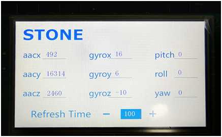
This program has a function to obtain euler Angle, just add it to the serial port displayer can be displayed.
In this program, the data displayed is raw data collected from MPU6050.
The connection mode of STM32, MPU6050 and the display screen is as follows:
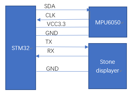
Please see the following picture for the operation effect:
Comments
Post a Comment